Monday, February 22, 2010

Home Automation (Receiver module)


This system is using battery 9Vdc and it will step down to 5V using LM7805 voltage regulator.

The voltage regulator module is used to protect PIC and other connected sensors or actuators from over voltage. This is because PIC and all other connected sensors, actuators all support 5V DC only. Over voltage will cause any of the module burn. LM7805 is used to regulate voltage in the system and output 5V DC (max current: 1000mA). It supports input voltage from 7V DC to 18V DC.

The output of each PIC pin is 5V with max output current of 20mA or 0V with 0mA output. The voltage is not enough to run high power device e.g. motor, solenoid. Thus we need a relay to control these high power items. A simple switching circuit (using NPN transistor, C9013) will be used to energize / de-energize the input coil of the relay.

Thursday, February 18, 2010

Remote (Transceiver module)


PIC16F877A microcontroller is used to control the whole system. It is designed using flash technology. So the PIC can read/write program for more than 100,000 times. The PIC can store up to 8Kbytes program. A program is downloaded into PIC through PIC programmer. This program will be used to operate the system.The PIC can operate using 4.5V to 6.0V DC voltage. In the project is operating at 5.0V (by using 7805). It is DIP layout (dual in line package) and suitable for student project. It has 40 pins but only 33 I/O pins can be set as digital input or digital output. The digital output of the PIC is 5V (for signal 1) and 0V (for signal 0) these signals will be directly connected to actuators for control purpose. When the PIC pin is set as digital input. It will detect input voltage 5V as signal 1 and 0V as signal 0. Any voltage less than 0V or more than 5V will damage PIC.

A normal LED use 5V and 5mA to operate. And through LED the current status of the system can be known. A 1KR resistor is connected series with the LED to limit the current pass through LED is 5mA. This is calculated using V=IR. Where V=5VDC, R=1KR. The LED will light on when the power is go through the circuit to alert user.

The variable resistor is to control the dimmer of the light and the speed of the fan. And as for the push button, it is for turn on or off the relay at the receiver module. When the remote is complete, only the push button will display on top of the remote.

Friday, February 12, 2010

Component that will use


PIC16F877A microcontroller is used to control the whole system. It is designed using flash technology. So the PIC can read/write program for more than 100,000 times. The PIC can store up to 8Kbytes program. A program is downloaded into PIC through PIC programmer. This program will be used to operate the system. The PIC can operate using 4.5V to 6V DC voltage. In the project is operating at 5V (by using 7805).


ZigBee is a standard for wireless data transmission just like Wi-Fi and Bluetooth. The entire device (wireless device) is function to move the desired data to the next carrier in the communications path until the data is delivered to the target end-point. MaxStream is a well-known manufacturer of components for wireless communication. ZigBee is one of the MaxStream products. There are two versions of ZigBee that are available from MaxStream which are XBee and XBee PRO. Both versions are functionally identical and pin compatible. The only difference is the transmit power, which is 1mW maximum for XBee and 63mW maximum for XBee PRO. ZigBee’s mission is to cut the traditional wires between sensors, wired slaves devices, and the microcontrollers and microprocessors they serve.


Battery is work as the supply power to the circuit so that the circuit can work at anywhere and anytime. The battery that is used in this project is 9v battery.


The voltage regulator module is used to protect PIC and other connected sensors or actuators from over voltage. This is because PIC and all other connected sensors, actuators all support 5V DC only. Over voltage will cause any of the module burn. LM7805 is used to regulate voltage in the system and output 5V DC (max current: 1000mA). It supports input voltage from 7V DC to 18V DC.


This regulator is to step down the voltage to 3.3v. XBee cannot accept the voltage larger then the 3.3v. If not, the XBee chip will be damage or burn. As for this project circuit, the PIC and other component such as LED can only accept 5v of voltage. So, the voltage need to be filter with this regulator to step down the voltage second time. First, step down the voltage to 5v using LM7805 regulator, then step down again the voltage to 3.3v using LM1086 regulator for the second time.


The variable resistor is to control the dimmer of the light and the speed of the fan. Variable resistors are often called potentiometers in books and catalogues. They are specified by their maximum resistance, linear or logarithmic track, and their physical size. The standard spindle diameter is 6mm.The resistance and type of track is marked on the body 4K7 LIN means 4.7 k linear track and 1M LOG means 1 M logarithmic track. Some variable resistors are designed to be mounted directly on the circuit board, but most are for mounting through a hole drilled in the case containing the circuit with stranded wire connecting their terminals to the circuit board.


A reverse diode 1N4007 is connected with input of relay to avoid reverse spike or over current flow back from the load. It also protects the circuit from over current load.


This selected bulb is easy to use and easy to put in the prototype.


This fan is selected because it is small and it suitable for the prototype.

Saturday, February 6, 2010

relay vs optocoupler


Connect the PIC to the relay or optocoupler to communicate from the remote to the home automation circuit. The problem is that I don't know whether to use the relay or optocoupler to connect from the PIC to light and fan. If I use the relay, the output just the LED but if I use the optocoupler, the output can be the the light(bulb) and fan(PC fan). This is because that the relay is a electronics switch. It's function as on and off to the LED.


A relay is an electrically operated switch. Many relays use an electromagnetic to operate a switching mechanism, but other operating principles are also used. Relays find applications where it is necessary to control a circuit by a low-power signal, or where several circuits must be controlled by one signal. A simple electromagnetic relay, such as the one taken from a car in the first picture, is an adaptation of an electromagnetic. It consists of a coil of wire surrounding a soft iron core, an iron yoke, which provides a low reluctance path for magnetic flux, a movable iron armature, and a set, or sets, of contacts; two in the relay pictured.


Optocoupler is a device that uses a short opticaltransmission path to transfer an electronic signal between elements of a circuit, typically a transmitter and a receiver, while keeping them electrically isolated since the electrical signal is converted to a light beam, transferred, then converted back to an electrical signal, there is no need for electrical connection between the source and destination circuits.The opto-isolator is simply a package that contains both an infrared light-emitting diode (LED) and a photodetector such as a photosensitive silicon diode, transistor Darlington pair, or silicon controlled rectifier (SCR). The wave-length responses of the two devices are tailored to be as identical as possible to permit the highest measure of coupling possible.


Sunday, January 31, 2010

Lamp, fan, home ventilation and radio..

For home automation, I've choose to make lamp, fan, ventilation system at home and radio become automatic.

The lamp is adjustable to control the dimmer of the light. As for the lamp, I've choose the DC lamp because this DC lamp is more practical then the AC. AC lamp such as the LED just can be use for the prototype and for the small used. But for the DC lamp such as bulb, it can be used direct to the house. But to connect the bulb to the PIC, I need to do the experiment on the voltage so that I can adjust the dimmer of the lamp.

For the fan, I make it automatic by control the speed of the fan from the remote control. The fan that I used for this project is just the laptop's cooler pad fan.

The home ventilation is just for the prototype. It just add another fan and make it move to the apposite direction so that the air will be absorb out from the prototype home.

And as for the radio, I still in the process to make it real. I mean that I still learning to make the radio can automatic on from the remote control.

Monday, January 25, 2010

Design circuit..


This is the basic circuit of my project. The function of this circuit is just to run the PIC16F877.

As you all know that the PIC16F877 can only receive maximum 5v of supply. If the supply is more then 5v, the IC will burn or damage. But in the real world, we can get the supply power from battery or adapter. Your adapter can be 9v to 15v and you cannot direct connect the power supply to the PIC, otherwise, your PIC will burn or damage. To overcome this problem, the regulator is used in this circuit because this regulator is function to reduce the power from high voltage to 5v. And I take 1000nF for the capacitor near the regulator because 1000nF is faster then 100nF to reduce the noise.

The LED near the regulator is function to alert me that there is power or not in the circuit by LED will on when there is a power and LED will off if there is no power in the circuit.

To set the reset button in this circuit, the switch button is connected to the MCLR pin of PIC16F877.

20 MHz crystal is used in this circuit because PIC16F877 peripheral said that this PIC can accept until 20MHz of pulse. If more then 20MHz, the PIC cannot run the program that burned inside them. Crystal is one of the important component that need to have in every circuit that used PIC or microcontroller. It is because this crystal is like a heart beat of the PIC. It control the pulse of the program inside the PIC. And I choose 20MHz because it is the fastest pulse that PIC16F877 can support and the program inside the PIC can be run faster then 8MHz or else.

Thursday, January 21, 2010

Home Automation

Actually, i forgot to explain about home automation. haha.. All those previous post is about zigbee and the function of xbee, the way xbee communicate with PIC and all the software that decided to use in this project with all the method. And now, I want to explain about home automation that already popular at USA but rarely use in Malaysia. In home automation, it can be build using wired or wireless. But I decided to use wireless because it can be install to the exist home and you no need to renovate your house just to install this application in your house. Wireless also easy to do maintenance. In this project, I've choose xbee as a wireless medium because it is current technology. ZigBee technology can minimizes the Wi-Fi and Bluetooth interference and also reduce amount of network traffic.

ok


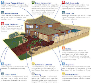
As you all can see picture above, all the things in the house can be automatic. You can control all the light, air-conditioning, surveillance or even watering the grass with using only one controller which can be in term of remote control or touch screen controller or it can be in the computer.

Look at this scenario. Each time you came back home, you need to switch on the light, fan or air-conditioner, and television. Each time you reach home, you need to walk out from your car and open the gate then go back to your car and parked it into garage then walk again to the gate an close it back. Or every week, you need to turn on the sprinklers and turn it off when it finish. But sometimes, you need to go out in the weekend and you forgot to turn it on and the result is your grass all lose their freshness. Or, your electrical bill is overdue because of unlimited usage of electric or forgotten to switch it off when you go out to work in weekdays or go back to your hometown in weekends. And you always feel uncomfortable to go outstation or go back to hometown or go to holiday because worried about your house if it save to leave all your belongings inside there. Sometimes, when you go back home, the environment of your house always the same and you got bored easily and stress because of that.

With this home automation application, all those problem can be solve easily. it is because home automation is design to make your home automatic. Such as turning on the sprinklers at a certain time every day and detecting burglars in the middle of the night. You can simply open the gate from your driver sit without need to move from your position or sensing the presence of the person in a room and adjusting light ambiance, the temperature in the room, the volume of the music, according to different factors like the day of the week and the time. The home ventilation also can be setup by certain time when you feel your home not in the fresh environment.